Photogrammetry transforms drone imagery into precise 3D models and maps, but success depends on understanding the technical foundations that drive accurate reconstructions.
🚁 The Foundation of Drone Photogrammetry
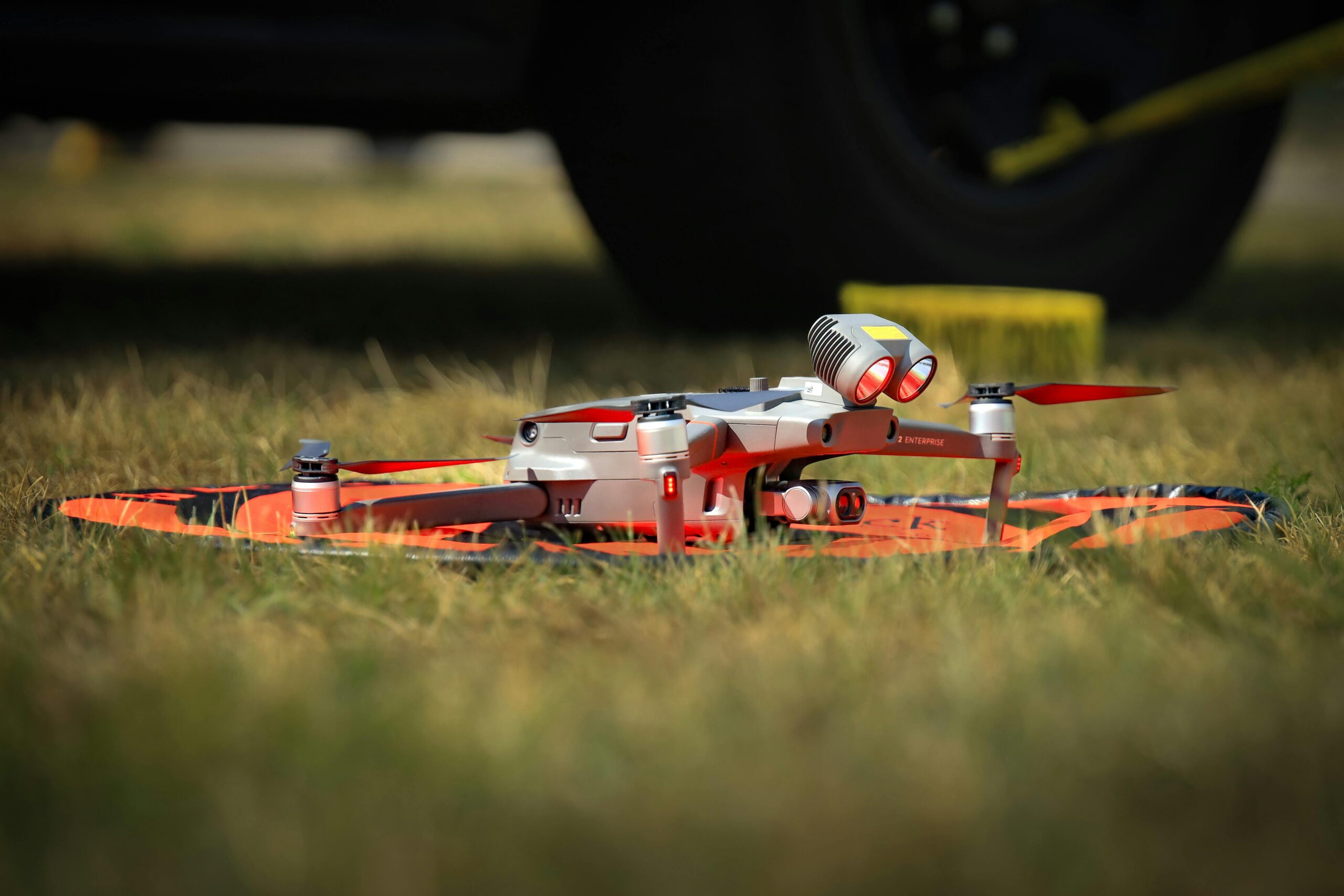
Drone photogrammetry has revolutionized how we capture and analyze spatial data. From construction sites to archaeological surveys, the ability to create detailed 3D models from aerial photographs has opened new possibilities across industries. However, the quality of your final output depends heavily on understanding the underlying processes that convert raw images into accurate representations.
At its core, photogrammetry relies on identifying common features across multiple photographs taken from different angles. This process, while conceptually simple, involves sophisticated mathematical calculations that determine the position, orientation, and internal characteristics of your camera at each capture point. Understanding these mechanisms allows you to troubleshoot problems, optimize workflows, and achieve professional-grade results consistently.
The journey from individual drone photographs to a finished 3D model involves several critical stages. Each stage presents unique challenges and opportunities for optimization. Whether you’re mapping agricultural land, documenting construction progress, or creating digital twins of infrastructure, mastering these fundamentals will elevate your photogrammetry work from amateur to expert level.
🎯 Understanding Tie Points: The Backbone of 3D Reconstruction
Tie points represent the fundamental building blocks of photogrammetric reconstruction. These are distinctive features that photogrammetry software automatically identifies and matches across multiple overlapping images. Think of them as anchors that connect your photographs into a coherent spatial network.
When your drone captures a series of images, each photograph contains thousands of potential features—corners, edges, textures, and patterns. Modern photogrammetry software uses sophisticated algorithms like SIFT (Scale-Invariant Feature Transform) or ORB (Oriented FAST and Rotated BRIEF) to detect these features and create unique descriptors for each one.
How Software Identifies and Matches Features
The matching process involves comparing feature descriptors across images to find correspondences. When the same physical point appears in multiple photographs, the software creates a tie point. The more images that contain a particular feature, the stronger and more reliable that tie point becomes for the reconstruction process.
Quality tie points share several characteristics. They should be well-distributed across the image area, not clustered in specific regions. They need sufficient contrast and distinctive patterns to ensure reliable matching. Weak tie points—those matched in only two images or those with ambiguous features—can introduce errors into your final model.
Optimizing Image Capture for Better Tie Points
Your flight planning directly impacts tie point quality. Maintaining 70-80% forward overlap and 60-70% side overlap ensures that each ground feature appears in multiple images. Flying at consistent altitudes keeps features at similar scales across images, making matching more reliable.
Lighting conditions significantly affect tie point detection. Shooting during overcast conditions or during the “golden hours” around sunrise and sunset provides even lighting without harsh shadows that can confuse matching algorithms. Avoid midday flights when possible, as strong overhead sun creates deep shadows and overexposed areas.
Camera settings also matter. Using a fast shutter speed (1/1000s or faster) prevents motion blur that degrades feature detection. Maintaining appropriate ISO levels preserves image detail while minimizing noise. Some practitioners prefer slight underexposure to preserve highlight detail in bright areas.
📐 Bundle Adjustment: Solving the Spatial Puzzle
Bundle adjustment represents the mathematical heart of photogrammetry. This optimization process simultaneously refines camera positions, orientations, and the 3D coordinates of tie points to minimize reprojection errors across the entire image network.
The term “bundle” refers to the bundles of light rays connecting each camera position to the 3D points visible in that image. Adjustment refers to the iterative optimization that adjusts all parameters to achieve the best overall fit to the observed image coordinates.
The Mathematics Behind Bundle Adjustment
Bundle adjustment solves a massive system of equations using non-linear least squares optimization. For a project with hundreds of images and millions of tie points, this involves minimizing the difference between observed feature locations in images and the predicted locations based on current estimates of camera parameters and point positions.
The process begins with initial estimates—often derived from GPS data embedded in your drone images or from approximate camera positions. The algorithm then iteratively adjusts all parameters, measuring how much each adjustment improves the overall fit. This continues until the solution converges, meaning further iterations produce negligible improvements.
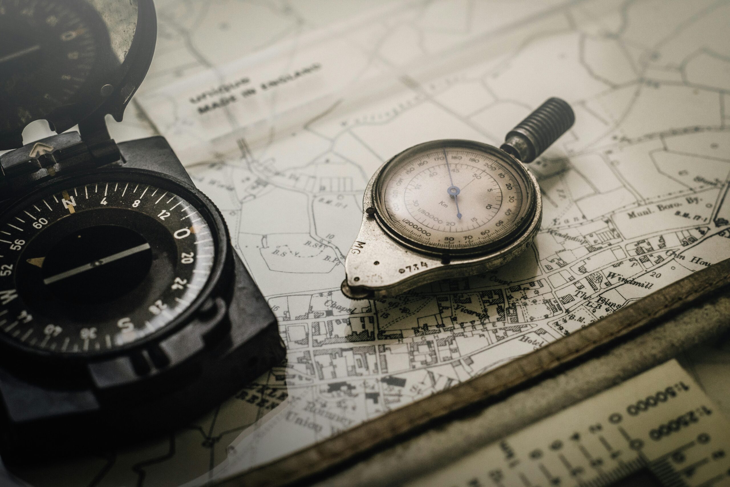
Ground Control Points and Their Role
Ground Control Points (GCPs) provide absolute spatial reference for your model. These are precisely surveyed locations visible in your images that anchor your reconstruction to real-world coordinates. While modern RTK-equipped drones reduce GCP requirements, understanding their role remains crucial.
During bundle adjustment, GCPs act as fixed constraints. The algorithm must satisfy both the photogrammetric relationships between images and the known positions of GCPs. This constrains the solution space and prevents drift, where accumulated small errors shift the entire model away from its true position.
Optimal GCP placement involves positioning points around the perimeter of your survey area with several in the interior. This geometry controls both horizontal and vertical accuracy. Placing all GCPs in a line or clustered in one area provides poor geometric strength.
Evaluating Bundle Adjustment Results
Photogrammetry software provides several metrics to assess bundle adjustment quality. Root Mean Square Error (RMSE) measures the average reprojection error across all observations. Lower values indicate better fit, though context matters—what’s acceptable depends on your project requirements and ground sample distance.
Camera calibration parameters refined during bundle adjustment reveal potential issues. Extreme values for radial distortion, principal point offset, or other internal parameters may indicate problems with your camera or flight execution. Comparing these values across multiple projects with the same equipment helps identify anomalies.
⚠️ Common Error Sources and Mitigation Strategies
Even with careful planning, various error sources can compromise photogrammetric accuracy. Understanding these issues enables you to recognize symptoms and implement effective solutions.
Systematic Camera Errors
Lens distortion represents one of the most significant systematic errors. While bundle adjustment estimates distortion parameters, extreme distortion—particularly in wide-angle or action cameras—can exceed what standard models accommodate. Using cameras designed for photogrammetry or implementing rigorous pre-calibration helps minimize these effects.
Rolling shutter effects plague many consumer drone cameras. Unlike global shutters that capture the entire frame simultaneously, rolling shutters scan from top to bottom. During flight, this creates geometric distortions that vary with drone velocity and shutter characteristics. Flying slower and using faster shutter speeds reduces rolling shutter artifacts.
Flight Execution Problems
Insufficient overlap creates gaps in your tie point network where adjacent images don’t share enough common features. Wind can push your drone off course, creating irregular overlap patterns even with properly planned missions. Always verify actual flight paths post-mission and consider reflying areas with poor coverage.
Altitude variations affect ground sample distance consistency. While most projects tolerate some variation, dramatic altitude changes—particularly over complex terrain—create scale differences that complicate matching and reduce accuracy. Terrain-following flight modes help maintain consistent ground clearance.
Environmental Challenges
Moving objects introduce errors since photogrammetry assumes a static scene. People, vehicles, or waving vegetation appear in different positions across images, creating inconsistent tie points. These outliers usually get filtered during processing, but extensive movement can compromise entire areas of your model.
Reflective or transparent surfaces pose significant challenges. Water bodies, glass, or highly polished materials don’t produce consistent features across viewing angles. These areas often appear distorted or incomplete in final models. Where possible, avoid flying when wet surfaces create specular reflections.
Textureless or repetitive surfaces cause ambiguous matching. Large uniform areas like bare soil, snow, or pavement lack distinctive features. Repetitive patterns like crops in rows or regular building facades create false matches. Adding temporary targets or adjusting flight altitude to capture more context helps in these situations.
🔧 Advanced Techniques for Accuracy Improvement
Multi-Flight Configurations
Combining nadir (straight-down) imagery with oblique (angled) photographs significantly improves reconstruction quality, particularly for vertical surfaces. The varied perspectives strengthen the geometry of your bundle adjustment and provide texture data for building facades and cliff faces.
Cross-grid patterns—flying perpendicular missions over the same area—enhance accuracy without requiring oblique imagery. This approach provides different viewing angles for the same features, improving the geometric strength of your network.
Adaptive Processing Parameters
Modern photogrammetry software offers numerous parameter adjustments that affect tie point detection, matching, and bundle adjustment. Understanding when to modify default settings separates advanced practitioners from beginners.
Adjusting keypoint limits affects processing time and quality. Higher keypoint counts capture more detail but increase processing time and may introduce noise. For highly detailed subjects, increasing keypoint density improves fine feature reconstruction. For broader mapping applications, default values typically suffice.
Matching thresholds determine how confident the software must be to accept a tie point match. Stricter thresholds reduce false matches but may eliminate valid tie points in challenging conditions. Relaxing thresholds helps in low-texture environments but requires careful quality checking.
Iterative Refinement Workflows
Professional workflows often involve multiple processing passes with progressive refinement. Initial processing with relaxed settings identifies obvious errors and outliers. Subsequent passes with tightened parameters and manual intervention address remaining issues.
Filtering tie points based on reconstruction uncertainty, reprojection error, or projection accuracy removes weak or erroneous matches. This cleanup typically improves final accuracy by eliminating points that contribute more noise than information.
📊 Quality Assessment and Validation
Quantifying accuracy requires independent validation data. Check points—surveyed positions not used as GCPs during processing—provide unbiased accuracy assessment. Comparing check point coordinates from your model against surveyed values reveals actual accuracy achieved.
Visual inspection remains invaluable despite sophisticated metrics. Examining your point cloud and mesh for obvious artifacts, distortions, or missing areas catches issues that numbers alone might miss. Pay particular attention to model edges, vertical surfaces, and areas with challenging features.
Understanding Accuracy Specifications
Absolute accuracy measures how closely your model matches real-world coordinates—crucial for projects requiring integration with existing survey data or infrastructure planning. Relative accuracy describes internal consistency—how precisely positions within the model relate to each other.
Many applications prioritize relative accuracy over absolute positioning. Change detection, volume calculations, and many inspection tasks care more about internal precision than global coordinate accuracy. Understanding your specific requirements helps optimize workflows and avoid unnecessary complexity.
🎓 Practical Workflow Integration
Implementing best practices requires integrating technical knowledge into streamlined workflows. Successful photogrammetry projects balance theoretical understanding with practical efficiency.
Pre-flight checklists ensure consistent execution. Verify camera settings, confirm mission parameters match project requirements, check weather conditions, and ensure adequate battery capacity. These simple steps prevent common errors that waste time and resources.
Post-flight data verification catches problems early when reflying remains practical. Quickly review image coverage, check overlap patterns, verify GPS data quality, and confirm image sharpness before leaving the site.
Structured processing workflows reduce errors and save time. Establish standard procedures for each project type, document parameter choices and their rationale, maintain processing logs, and archive raw data systematically.
🚀 Future Developments and Emerging Techniques
Photogrammetry technology continues evolving rapidly. Machine learning increasingly enhances feature detection and matching, particularly in challenging conditions. Neural network approaches show promise for handling difficult surfaces and improving processing speed.
Real-time processing capabilities are emerging, allowing preliminary assessment during flight. This enables adaptive mission planning where initial results inform subsequent capture strategies, maximizing efficiency and accuracy.
Integration with other sensing modalities—LiDAR, multispectral, thermal—creates rich datasets combining geometric precision with additional information layers. Understanding photogrammetric fundamentals provides the foundation for effectively utilizing these hybrid approaches.

🎯 Mastering Your Photogrammetric Journey
Excellence in drone photogrammetry emerges from understanding the complete workflow from image capture through final deliverables. Tie points form the connective tissue linking images into coherent spatial networks. Bundle adjustment refines this network through sophisticated mathematical optimization. Recognizing and mitigating error sources ensures reliable, accurate results.
Start with solid fundamentals—proper flight planning, appropriate overlap, good lighting, and sharp images. Build understanding through experimentation, comparing results across different approaches. Study your processing reports, understand what the metrics reveal, and develop intuition for recognizing problems and solutions.
The field rewards continuous learning. As drone technology advances and software capabilities expand, practitioners who understand underlying principles adapt most effectively. Whether you’re mapping construction sites, documenting heritage structures, or analyzing environmental change, mastering photogrammetric fundamentals unlocks the full potential of drone-based spatial data collection.
Your expertise develops through the combination of theoretical knowledge and practical experience. Each project teaches new lessons about specific challenges and effective solutions. By understanding how tie points, bundle adjustment, and error sources interact, you gain the insight needed to consistently produce professional-quality photogrammetric products that meet demanding accuracy requirements across diverse applications.